dBricks software and its addons enable avionics developers to create system interface models. The ready-to-use interface model allows to generate various documents and create system models for the following development areas:
dBricks guarantees alignment of imported and exported data, while our approach eliminates the need to enter and store the same information all over again. Automated data integrity and validation checks incorporated in dBricks ensure complete and unambiguous interface description.
Last decades innovations in avionics development have provided unprecedented growth of flight safety, convenience of pilots and flights timely departure. But the downside of high-tech intelligent airborne systems is design complexity.
Airborne systems engineers face an extremely difficult task of integrating a huge number of components (which already are complex per se) into a synergy that should work as a single whole. The task is further complicated by the need to provide the highest standards of safety and comply with numerous industry standards.

Development of complex airborne systems cannot do without preparing numerous documents, such as:
Usually, the aforementioned documents are big, they contain project implementation details: from wires to digital bus parameters refresh rates. In order for the resulting equipment system to operate fault-free and to be certified by aviation authorities, all documents should be consistent and comply with industry standards, regulatory documents, aircraft and avionics requirements.
The challenge of documentation consistency is a consequence of modern avionics complexity in general and the fact that a dozen of departments within the aircraft manufacturer company and dozens of external OEM companies are involved in this documentation development. Organizing effective interaction of all the resources involved in the process is a non-trivial task both from the technical and organizational points of view.
Aircraft (AC) development is governed by AC technical and functional requirements, AC certification requirements (certification basis), applicable state and industry standards, AC manufacturer and OEM's internal standards. All these requirements must be consistent; traceability to them must be controlled (if possible by automatic means).
The initial design data alongside with requirements and regulations includes a large amount of information exchanged between the AC manufacturer and OEMs. These initial data change at different design stages as well as at the stages of testing, trials, certification, and even during the aircraft operation. Controlling the coordinated change of all systems and equipment affected by the initial data changes is one of the aviation equipment development most time-consuming tasks.
Unfortunately, progress in the field of avionics as such has not touched on the avionic equipment (AE) development tools, and engineers are compelled to conduct their projects in an old-fashioned way in a spreadsheet and text editors, such as Microsoft Excel and Microsoft Word. These editors, although being convenient and powerful tools for creating documents, are not designed for airborne equipment development, since they do not allow controlling integrity, applying changes throughout the project simultaneously, providing multi-user access to the project being developed, etc.
The result of the absence of specialized tools is the need to perform a huge amount of work on a thorough inspection and manual configuration management of documents being developed and modified, which can lead to delays and/or errors.
The existing problem in avionic equipment development processes is recognized by the majority of specialists involved, but the automation tools of the processes described above are not yet available on the market.
The purpose of the dBricks tool is:
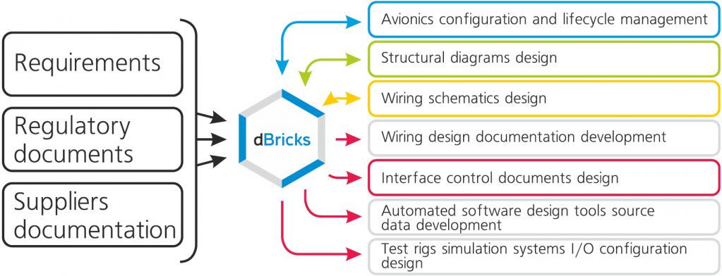
The tool's purpose is achieved by means of the following processes automation:
The dBricks tool is developed on the basis of the vast experience gained during the work on all modern projects of civil airliners in the Russian Federation.
The idea of using automation tools for AE development processes emerged during the work on flight instruments of IL-96, TU-204 and IL-114 aircraft. At the same time, the first basic tools for the development of Interface Control Document and wiring lists and schematics were developed.

Alexander Mishin, CC BY-SA 3.0 GFDL, via Wikimedia Commons
Later, the tools were further developed and expanded for the automated generation of aircraft circuit diagrams, connection diagrams, interface control documents and other documents used in the manufacture, installation and development of the cable net and AE of the SuperJet-100 aircraft (RRJ-95). With the help of these tools, data were also obtained for automated assessment of the stability of the complex against external factors influence including HIRF, and analysis of the aircraft's equipment fail-safety.
Upon completion of the development of the SuperJet-100 a further step was made to connect disparate tools into a single unified system with enhanced functionality. Today the results of these works are widely used in the development and trials of avionic equipment of the MS-21 aircraft.
The dBricks tool is the ideological successor of all the aforementioned stages of automation tools development, which has incorporated all the gained experience and knowledge on the topic.
The dBricks system is made out of a normalized database and means of data input, output and modification.
The tool works on client-server technology. Server-side includes network storage and server module. Server module interacts with the client module with regard to processing input data and prepares data for visualization by the client module.
The client module is a graphical shell intended for displaying data received from the server and providing convenient access to the data. dBricks client part is implemented as a web page accessed through a web browser (e.g. Google Chrome).
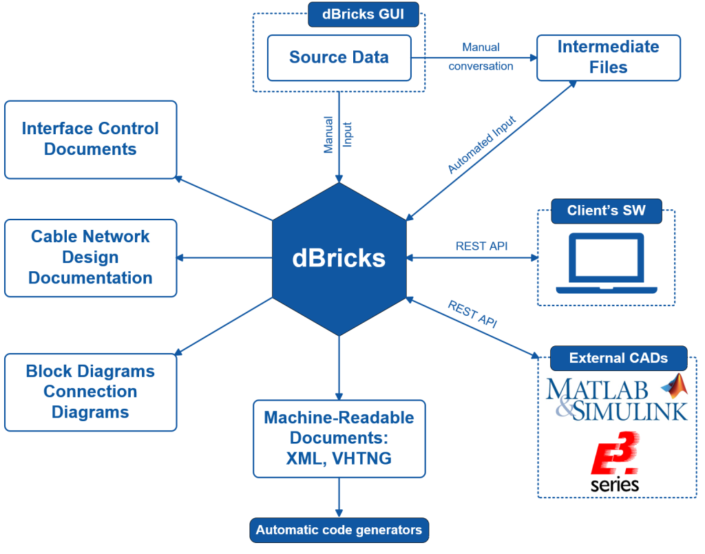
Following the idea of data normalization, the dBricks system considers data describing avionic equipment not as a single entity, but as an object consisting of other objects and connections between them. The objects that make up a project, in turn also consist of smaller objects and connections between them. Using a normalized approach completely eliminates the need of repeated entering and storing the same type of data, including when using the same versions of devices in different projects.
Below are three global object families:
The dBricks tool is implemented on client-server architecture, which allows the entire project team to work with the tool simultaneously. This fact is one of the main advantages of the tool. Once the tool is deployed, the most up-to-date information about the status of the project is always available to each project stakeholder. Any changes made by one user automatically become available to everyone. Depending on the Customer's need the tool can be installed in such a way that it will be available not only to the employees of the company but also to employees of contractor companies. Information security and unauthorized access control are provided by a flexible system of access rights control. The system also provides logging of all user actions, which allows finding the author of each change.

The tool is developed hand in hand with end-users and developers of the AC AE. In the course of development, dozens of suggestions from users were accounted in the user interface. The main technical solutions are tested on the data of the real project. Tools and speed of the system enable effective work with projects of modern airliners containing hundreds of devices, tens of thousands of wires and hundreds of thousands of parameters.
For the purposes of input and editing large volumes of data, the tool provides the mechanism of bulk data input/editing, which allows reducing the complexity of the task by orders.
During the development of complex AE projects, it becomes necessary to manage the configuration of multiple versions of the project, arising both from the variability of the project itself (for example, the implementation of options) and because of the need to track the generations of the complex developed with different sets of requirements (rig tests version, first flight version, certification version, etc.). dBricks uses a configuration management mechanism that allows performing the following functions:
Using the tool allows eliminating the significant number of errors that are introduced upon data input. The system allows filtering out errors that violate the requirements of regulatory documents, industry standards and customized project limitations. Errors that violate the requirements of regulations and standards include but are not limited to attempts to connect different types of buses or attempts to include data in the data exchange description that cannot be physically realized. Errors that violate configurable project limitations may include violation of the naming convention or restrictions on the accidental connection of parameters with different data types.
The tool with a populated database allows you to automate the following processes.
Note: Generally speaking, once the tool is deployed the implementation of these processes is reduced to populating the database. Once the database is populated the resulting documents are created automatically.
The diagrams listed are the main documents describing the connection of AE devices to each other. The tool allows generating the diagrams in an automated fashion. The result of the export is the completed diagram file in Microsoft Visio format.
ICD development is one of the fundamental task of the entire AE development effort and one of the main purposes of the dBricks tool. The tool allows export of ICD for data exchange implemented through the following types of interfaces:
In addition to work effort reduction the automated ICD export facilitates elimination of human errors emerging when manually creating the documents.
Note: ICD export format can be customized based on customer requirements. Out of the box dBricks contains export to Microsoft Excel format
In modern projects development of flight software responsible for information input and output is usually produced with specialized equipment manufacturers CAD, based on special format spreadsheets. The presence of complete information on the equipment interaction in the dBricks system makes it possible to prepare the relevant spreadsheets by simply converting the information into the specified format. Through this the possible sources of transfer errors are eliminated and table preparation time is reduced.
Flight software specifications are the documents that fully describe functional requirements of airborne equipment processing modules. The dBricks tool allows generating such documents automatically based on data stored in the database.
In modern data networks such as ARINC 664 the configuration of information flows is described by configuration files that are uploaded to data exchange nodes. Such files can also be automatically generated by the tool based on data put into the database.
Note: Detailed description of the configuration requirements is given in ARINC 664 part 7.
Traditionally development of cable nets design specifications (CNDS) for test bench and flight training devices (hereinafter referred to as test benches) was a very time-consuming task coming from the large number of errors that appear in the process of converting the aircraft data into documentation adapted to create test benches. Using the dBricks tool allows to:
The airborne data acquisition systems used in aircraft testing process and the maintenance system are very similar in terms of data exchange. The presence in the dBricks system of complete information about the pick-up points and the formats of the information transmitted by the systems allows to automatically create registration system input devices requirements according to the nomenclature and the number of receivers, connection tables and information formats for its processing
During test benches and flight training devices (hereinafter referred to as test benches) development there is a need to describe the data exchange of equipment simulators not present on the test benches. Typically test bench simulation systems can be configured through specialized configuration files. Automated creation of such files based on the data entered during the development of ICDs allows to completely eliminate errors in the development of the files, as well as to reduce the labor cost of the process by 95-99%.
The presence of integrated information on all aircraft equipment, including support systems (electrical system, hydraulic system, etc.), its location in the aircraft and interconnection allows implementing several important analytical functions:
Depending on Customers' need the tool can be used in one of the ways listed below.
When working with the tool as an Internet service, the Customer gets access to a copy of the software, deployed by the Vendor in the cloud. Access is granted during the period paid by the Customer, and is automatically renewed given that the next period is paid on time. At Customer's request, after switching to the option of installing the tool on the Customer's local server, the work results obtained with the in-cloud tool instance can be transferred to the tool installed on the Customer's local server.
This method involves installing the tool on a server hosted by the Customer. The license term is unlimited subject to the terms of the license agreement. Software technical support and updates are performed during the period of technical support specified in the license agreement. The technical support period can be extended on the terms specified in the license agreement and maintenance contract
Depending on Customer's needs, the tool functionality can be customized by adding/removing the following modules and extension packages:
The basic module is an integral part of the tool.
The module implements the following functionality:
The basic elements for which the CRUD functionality is implemented include:
EI functionality for basic elements includes EI of:
The functionality of data input restrictions control allows:
The basic reports implemented in the module include:
The module allows to CRUD information for the following bus types:
The module also implements the export of ICD by buses types listed above.
The module is designed to work with ARINC 429 bus data. The module implements the following functionality:
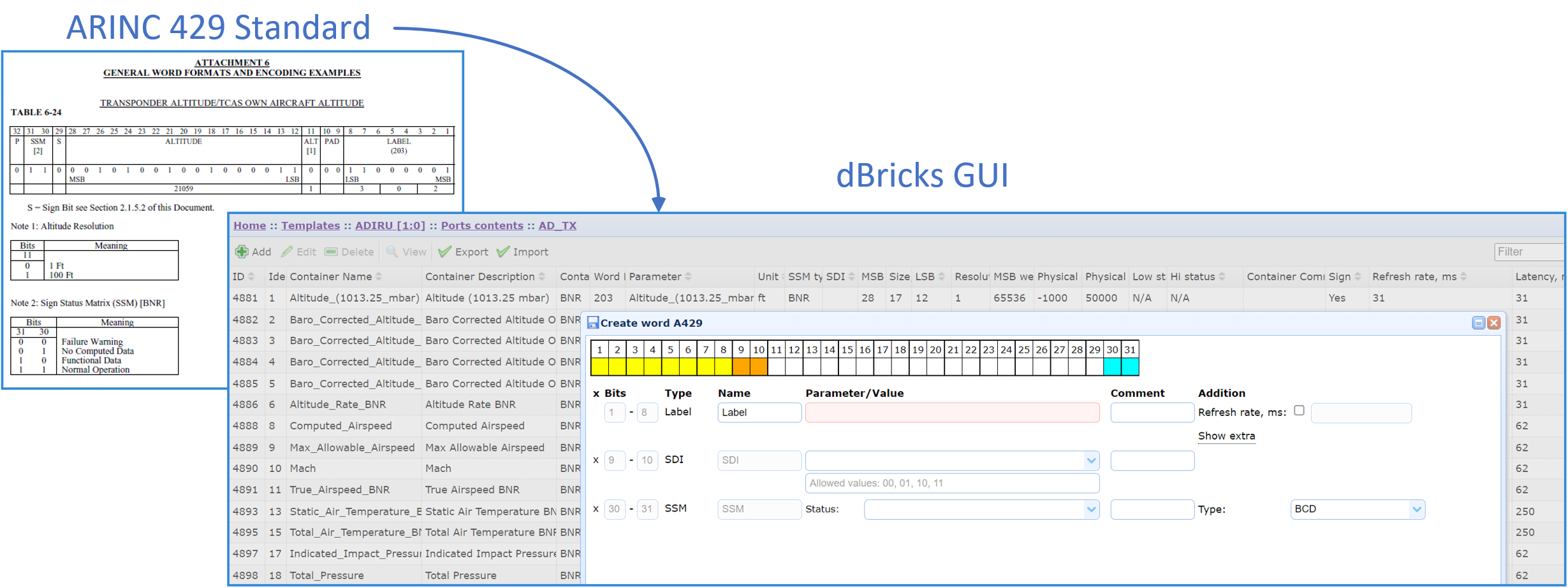
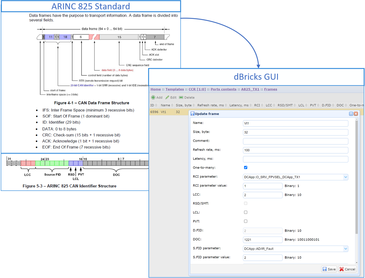
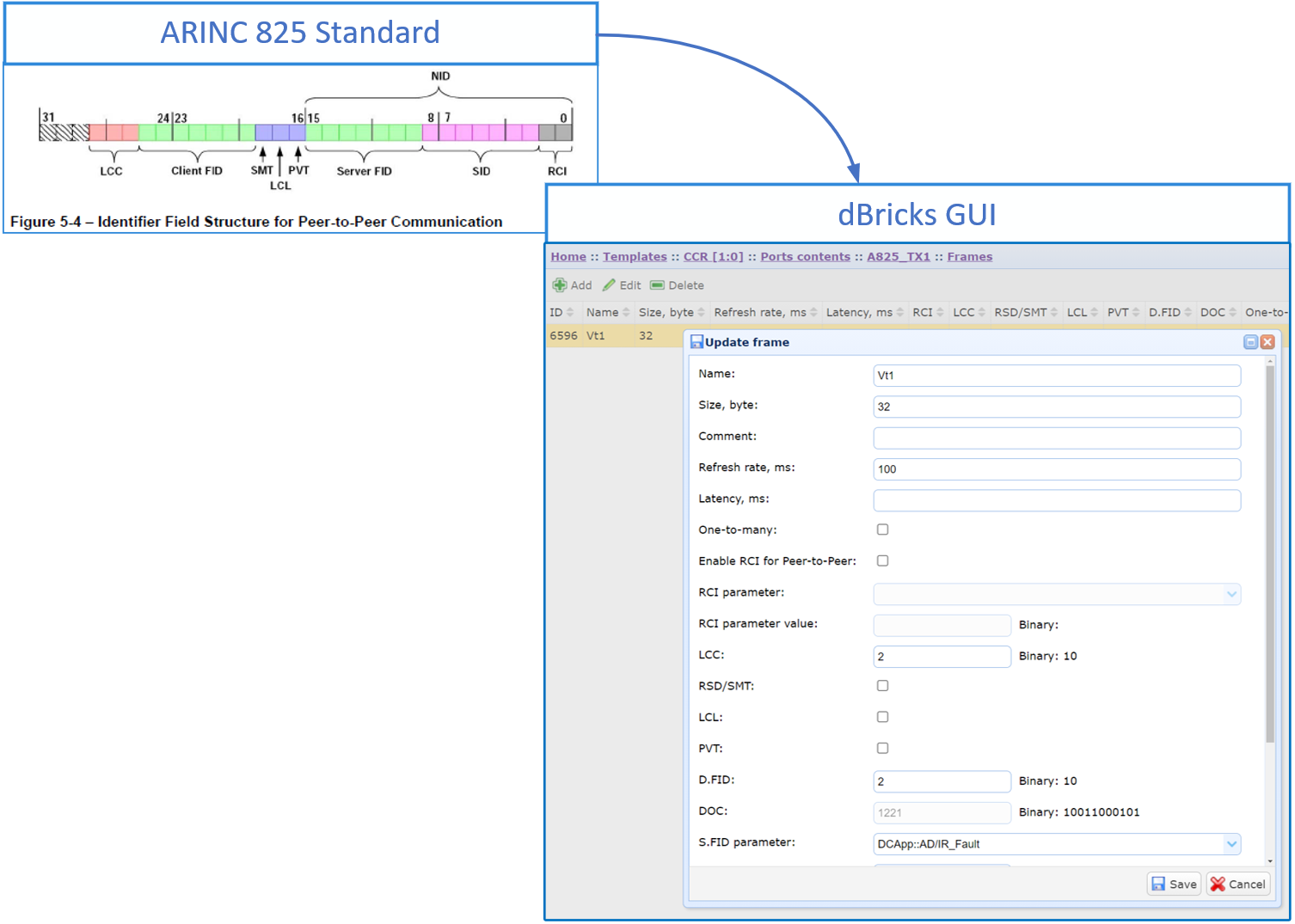
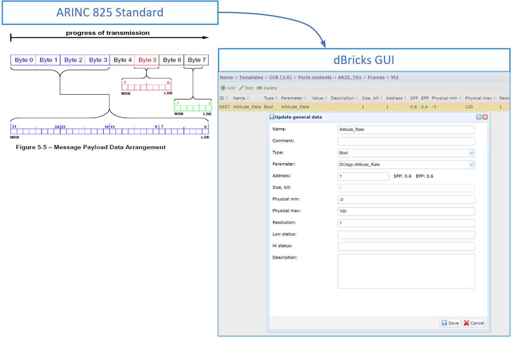
The module is designed to work with ARINC 825 bus data. The module implements the following functionality:
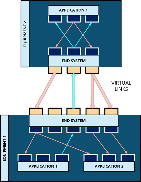
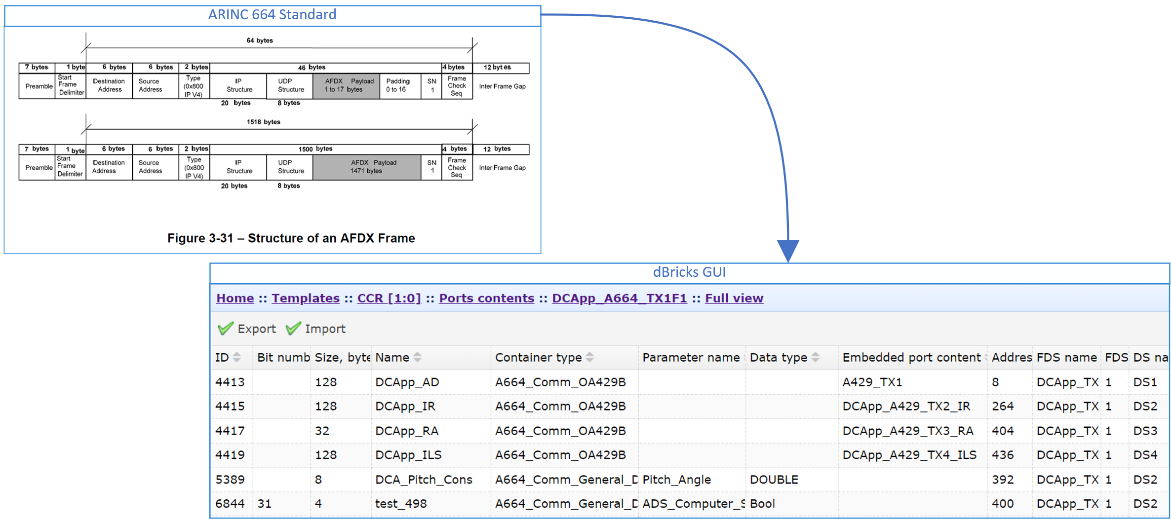
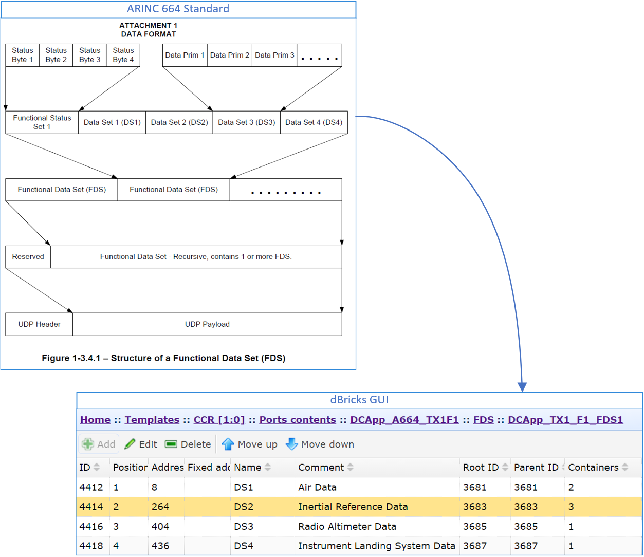
The module allows you to create descriptions of ARINC 664 (AFDX) data transfer which includes descriptions of the structures of the information exchange ports of the onboard software (application ports/partitions in terms of the ARINC 653 standard):
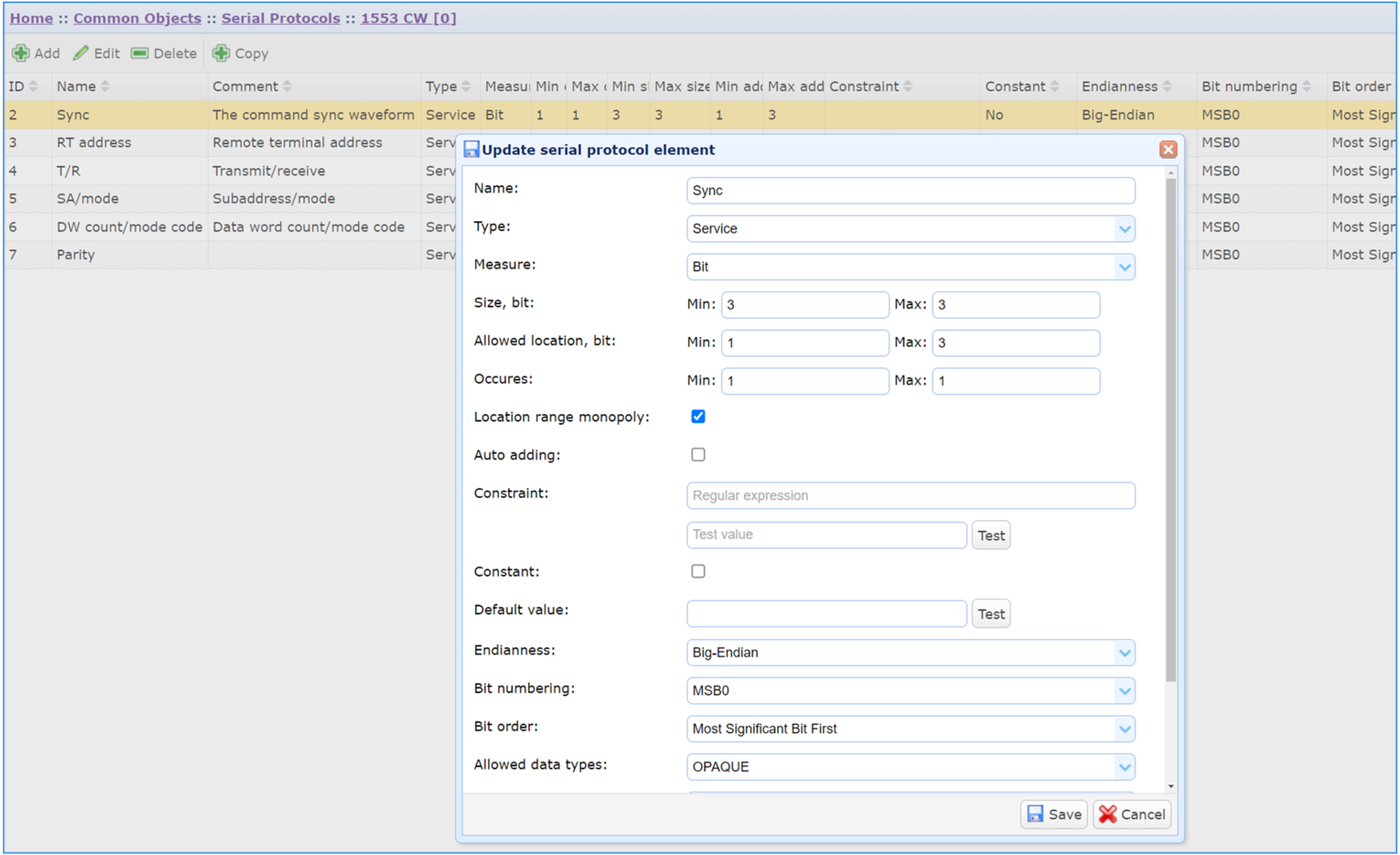
The module allows you to create descriptions of arbitrary serial exchange protocols on your own without specialized modifications to dBricks. For example, it is possible to describe common serial data transfer protocols, for which only restrictions on the physical layer are defined:
The module implements generation of block diagrams and connection diagrams in Microsoft Visio format.
Examples of the automatically generated diagrams in MS Visio:
Structure diagram (ASME template)
Connection diagram (ISO template)
The module is intended for designing the cable network topology of the buses. This module allows you to transform the functional diagram bus connections to physical layout connections into the cable network. The module implements the following functionality:
The result of this design is a set of initial data for the harness topology development:
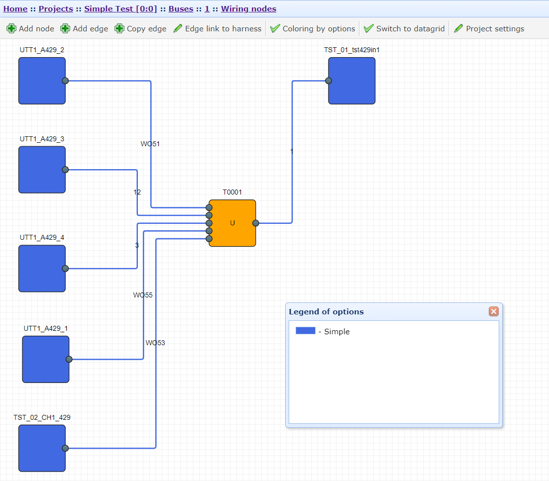
Graphical editor for cable network topology development. Example of splitting a bus into cable segments.
The module is intended for harness cable network development and harness documents set generation. Initial data for harness development is the outcome bus design of Cable network topology development Module. The following functionality is included:
CRUD of harness configuration specifying:
Automatic link of bus wiring edges to appropriate harnesses
CRUD of harness topology in build-in graphical editor
Automatic generation of the harness document set for harness production in MS Visio and MS Exсel formats in accordance with ISO, ASME standards.
Harness document set, generated using harness development Module, includes:
Documentation format and file type can be changed and modified according to customer requirements.
Graphic editor for harness development. Example.
Example of Assembling drawing
Example of Parts List
Example of Table of Connections
The module is intended for generating the Interface Control Documents (ICD) between the project devices arbitrarily selected by the user, in the form of a ready-made MS Word text document. The ICD includes a data transfer description of the following interface types:
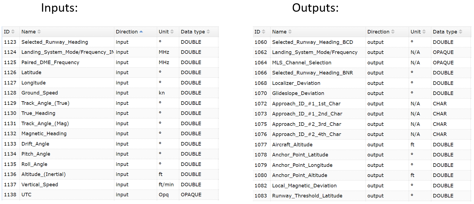 dBricks Toolbox creates FIM in Simulink with these IO parameters according to dBricks data:
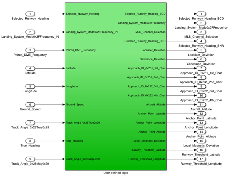
Example of Automatically Generated FIM inputs/outputs in Simulink
Automatically generated input/output parameters used by models to interface with each other are in white; section for user defined logic description for automatically generated model is in green. FIM contains Simulink ports that correspond to the list of input/output parameters of ILS function of MMR unit designed in dBricks. Simulink ports names, sequence, and properties were predetermined in dBricks, in particular:Unit Interface-Model (UIM) consists of logic and transport layers.
Logic layer is a set of FIM.
Transport layer corresponds to:
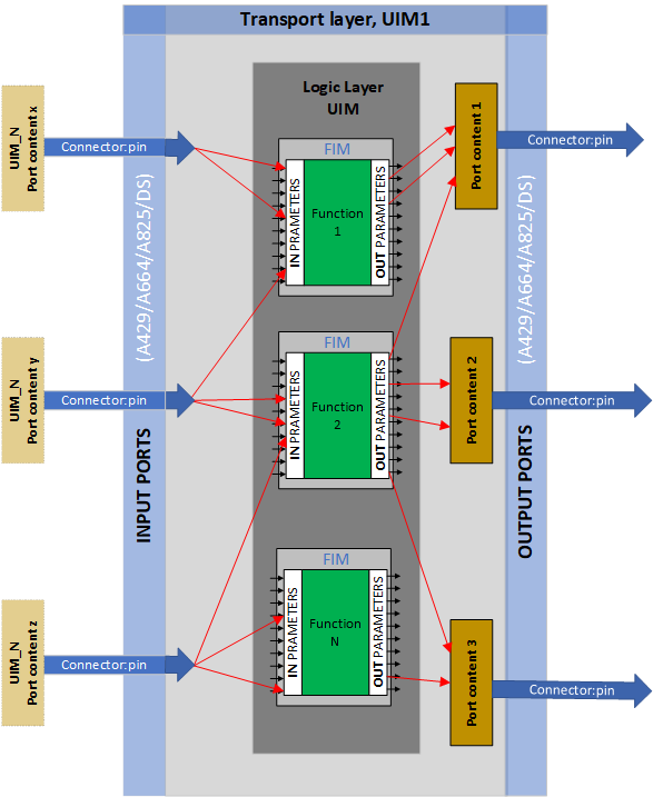
UIM Schematic
Example of A429 port content:
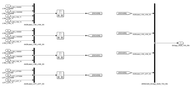
Example of ARINC 429 UIM Port Content in Simulink
dBricks Toolbox allows to develop AE data exchange models based on:
E.g. let’s consider an aircraft scale project: there are hundreds of thousands of parameter links between devices. To connect FIM/UIM parameters manually and control the conformity of data exchange between models in dBricks is an extremely hard task for such a project. Since there is no direct integration between dBricks and MATLAB, FIM interfaces, data exchange models and information stored in dBricks will inevitably diverge over time. dBricks and dBricks Toolbox for MATLAB/Simulink resolve this issue by providing the user an opportunity to check FIM interfaces according to the updated data in dBricks.
The module is designed to generate configuration files for the information exchange model of a device, systems or the entire complex from dBricks for semi-natural simulation stands. A configuration file is any machine-readable file with a predefined structure. For example, the configuration of information exchange in the VHTNG standard (Virtual Hybrid Testing Next Generation project), which is a machine-readable xml file. VHTNG files are used to configure semi-natural simulation benches. You can read more about VHTNG at https://www.sae.org/publications/technical-papers/content/2018-01-1949 or see examples of using the VHTNG module by TechSAT https://techsat.com/systems-and-solutions/development-virtual-integration/ed-247-vistas/.
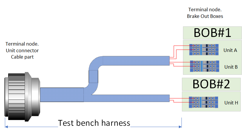
The toolbox implements functionality of automatic generation of configuration files used to configure test benches and flight simulators simulation systems. List and format of files varies depending on the equipment used by the Customer, but usually includes the following main groups of files:
The technical support of the tool consists in the listed below services provided by the Vendor. For license agreements that provide access to the tool as an Internet service the technical support is provided during the whole period of access to the tool. For license agreements that account for the installation of the tool on the Customer's local server the technical support is provided during the time specified in the license agreement and maintenance contract.
The support consists in providing voice consultations for Customer's representatives by the phone specified in the contract.
Unless otherwise specified in the contract, consultations are provided from 10:00 to 18:00 Moscow time on weekdays determined in accordance with the legislation of the Russian Federation.
Unless otherwise specified in the contract, the total amount of consulting should not exceed 10 hours per month.
The support consists in providing answers to Customer questions sent to the e-mail address specified in the contract.
Unless otherwise specified in the contract, the deadline for answering questions is two business days determined in accordance with the legislation of the Russian Federation.
Support consists in registration, processing, resolving and/or provision of a reasoned correction refusal, on the basis of Customer comments in the bug tracking system (located at the URL specified in the contract).
The response time to comments depends on the error severity. The existing error severity levels are:
Note: Response time is not the time to fix the problem or correct the error.
During the technical support period the Vendor provides the Customer with information on available new versions of the tool. At the Customer's request the Vendor can upgrade the tool to the latest available version.
The dBricks system allows to:
 Developing a Simple System with dBricks. Video#1 (Here you can see how to develop a simple system in a few minutes.)
 Developing a Simple System with dBricks. Video#2 (Here you can see how to update your simple system with a data transport layer and logical links between the devices in a few minutes.)
 dBricks Booklet
 dBricks Overview (This document provides an overview of the purpose and main functions of dBricks)
 dBricks Use Case Examples
 Designing Interfaces for Complex Engineering Systems: From Wire to Bit (Acquaintance with the main functions of DBR in presentation format)
 Avionics Equipment Integration Test Benches. Design Proposal (This document sums up the relevant experience of PEERSS engineers gained in several CS-25 certified aircrafts projects.)